PartWorks 3D tutorial
Partworks 3D is one of the options to turn 3D models into gcode for the Shopbot. Creating toolpaths in PartWorks 3D is pretty straightforward: there’s 7 steps that the program guides you through and the steps are visualized conveniently.
Steps
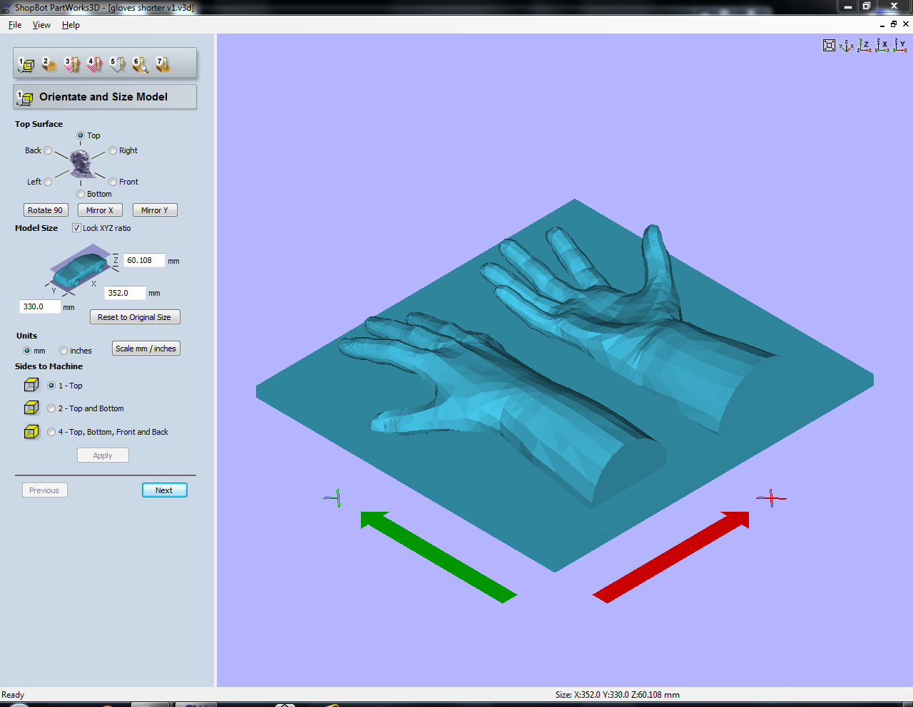
1. Orientate and Size Model
Start with importing the 3D model (stl/obj). Specify orientation and size of the model. You can change the top surface of the model. Top has been selected here since the model had been designed with the machine’s orientation in mind. The model can be scaled here if you haven’t done so already. Always check if the size corresponds to your design. Select Top for Sides to Machine and press Apply.
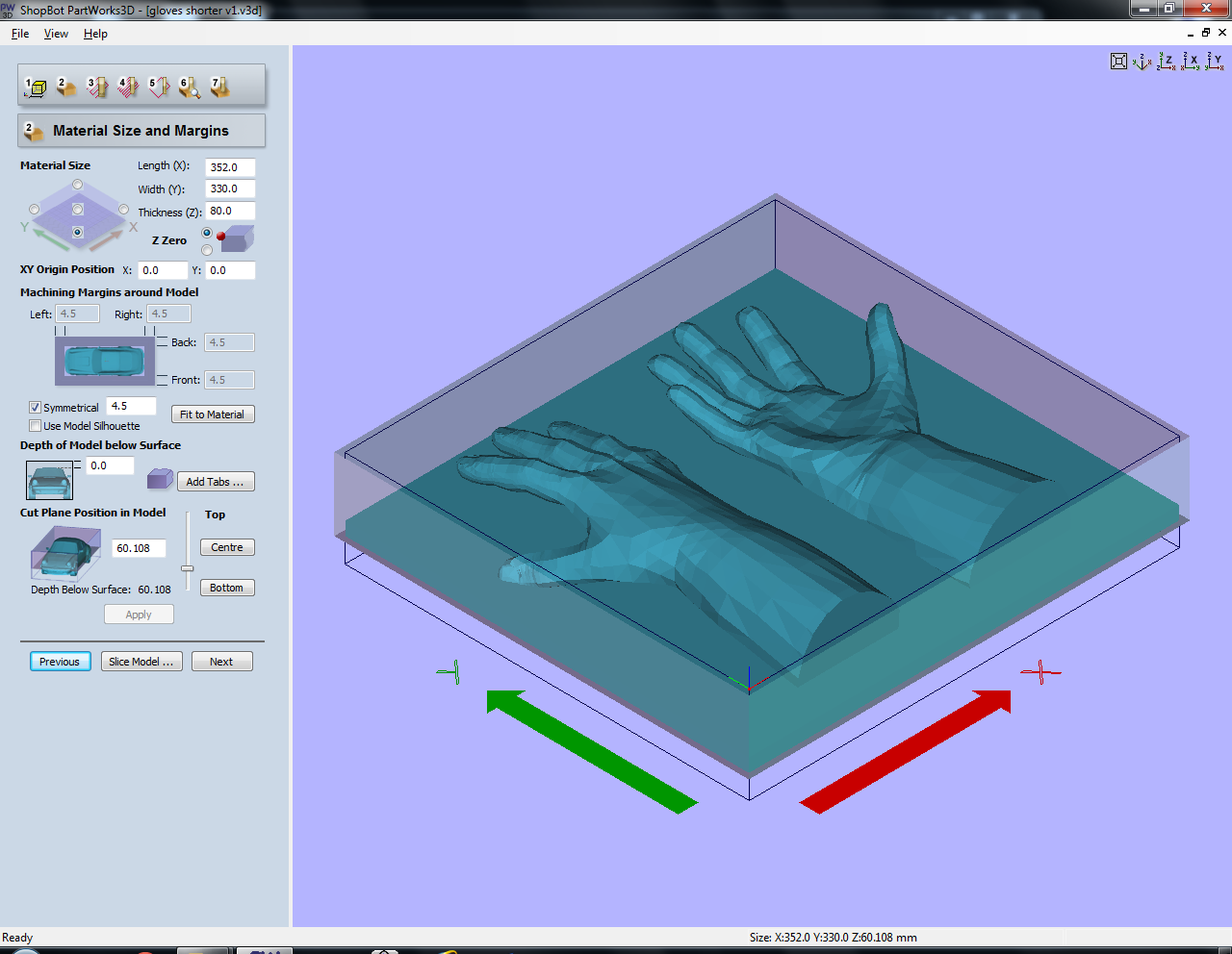
2. Material Size and Margins
You can fool the machine by setting the material size to the model size, then you just zero the X and Y on the Shopbot where you want to start milling. If your material is thicker than your model you also don’t have to specify this, if you zero Z at the top of the material. Set the XY zero position. If necessary you can add margins. The Cut Plane Position in Model specifies the depth below the surface of the material. Unless the top surface of your material is very irregular, place your model as high as possible, so milling will go faster. Press apply when finished.
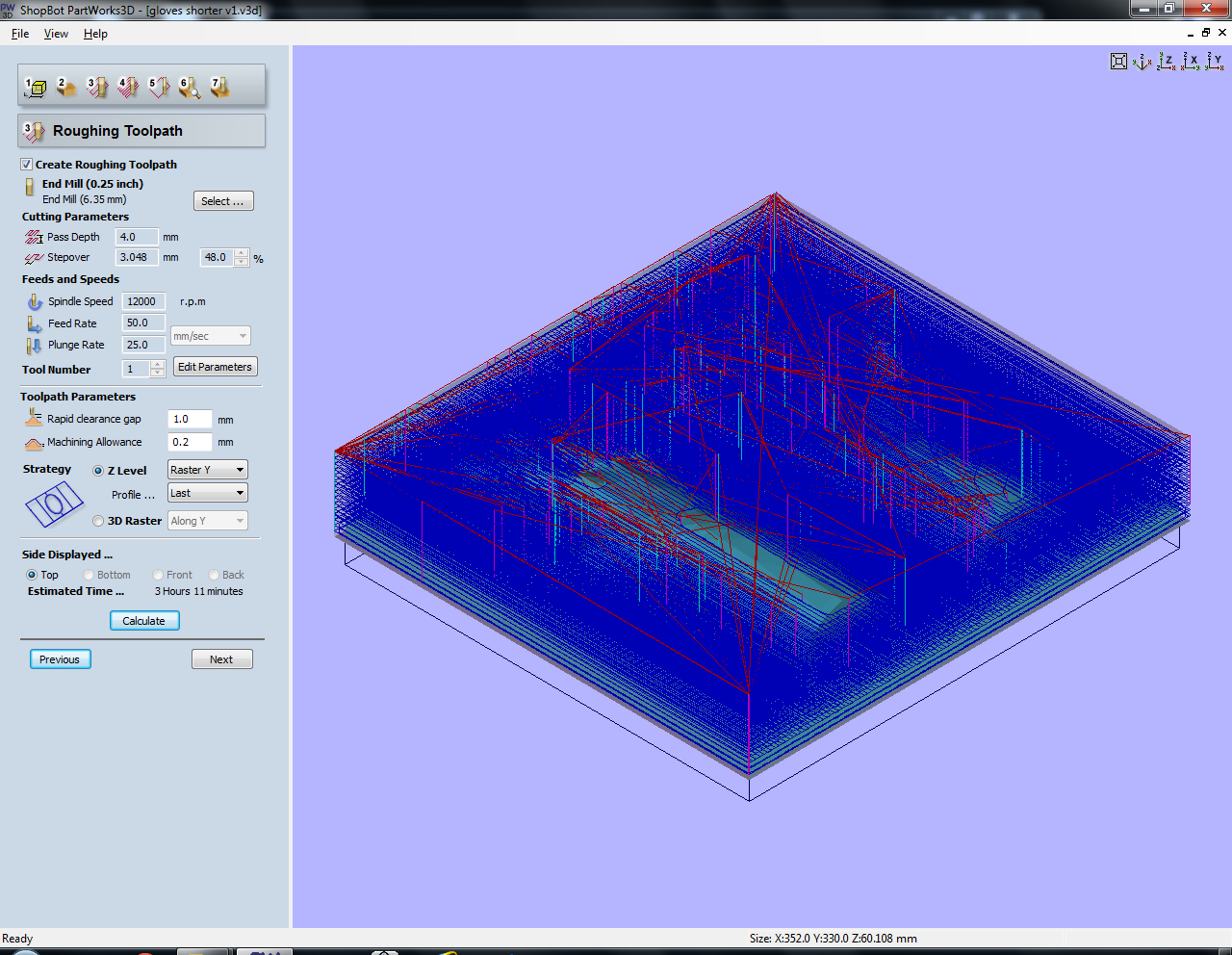
3. Roughing Toolpath
This is the first run of the machine, where it mills away material layer by layer, top to bottom. Select the milling bit you want to use. Here a quarter inch four flute end mill was used, because this was the only long end mill we had in the lab. Normally we only use the metric mills, only if there’s no other way to do your project you can ask to use an imperial mill. Values used here:
- Spindle speed of 18000 RPM (not 12000 as specified in the screenshot)
- Stepover of 48%
- Pass depth of 4mm
- Plunge rate of 25mm per second
- Feed rate: when using a four flute mill, the feed rate has to be lower than usual (120mm per second is usually fine for foam with a two flute) since it takes more time for a four flute to get rid of the material. In this case the feed rate was increased from 50mm to 80mm per second while milling since it didn’t seem to have any issues with milling the foam.
Machine allowance is how much material is left to sand away. Rapid clearance gap is the height above the material when traveling. Using an Y-raster strategy is easier for the machine as the bridge doesn’t have to move constantly. Press calculate to get an estimate of milling time.
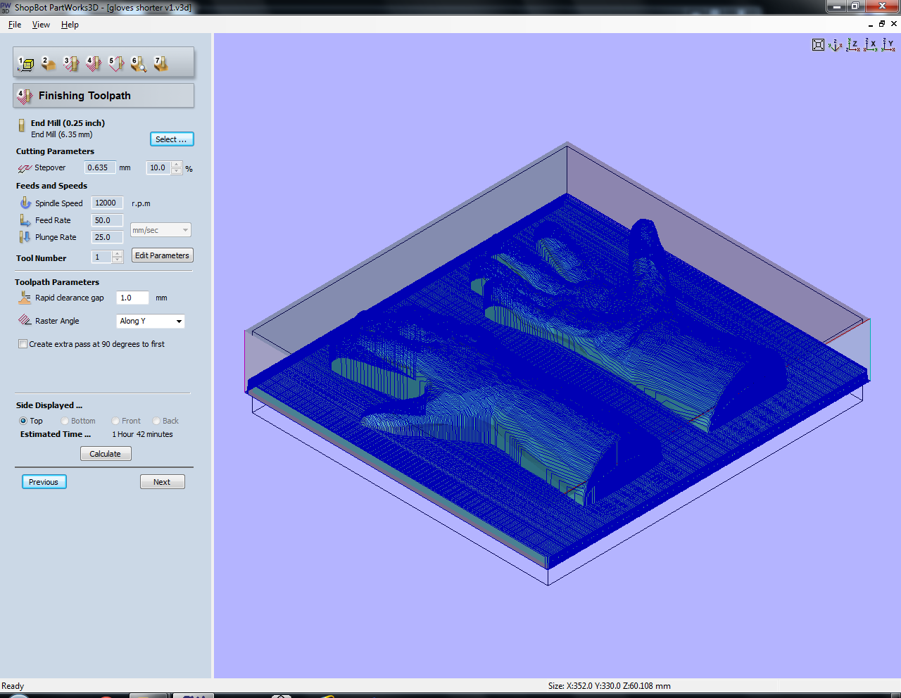
4. Finishing Toolpath
This is the second run of the machine where it mills away material in a non-planar fashion. You can change the mill to one with a smaller diameter or to a ball nose mill. Using a raster angle along the Y axis is again easier for the machine (and slightly faster). The stepover is much smaller here: the smaller the stepover, the higher the resolution. A spindle speed of 18000 RPM was used (again, not 12000 as specified in the screenshot), a stepover of 10% and plunge rate of 25mm per second. Then press calculate.
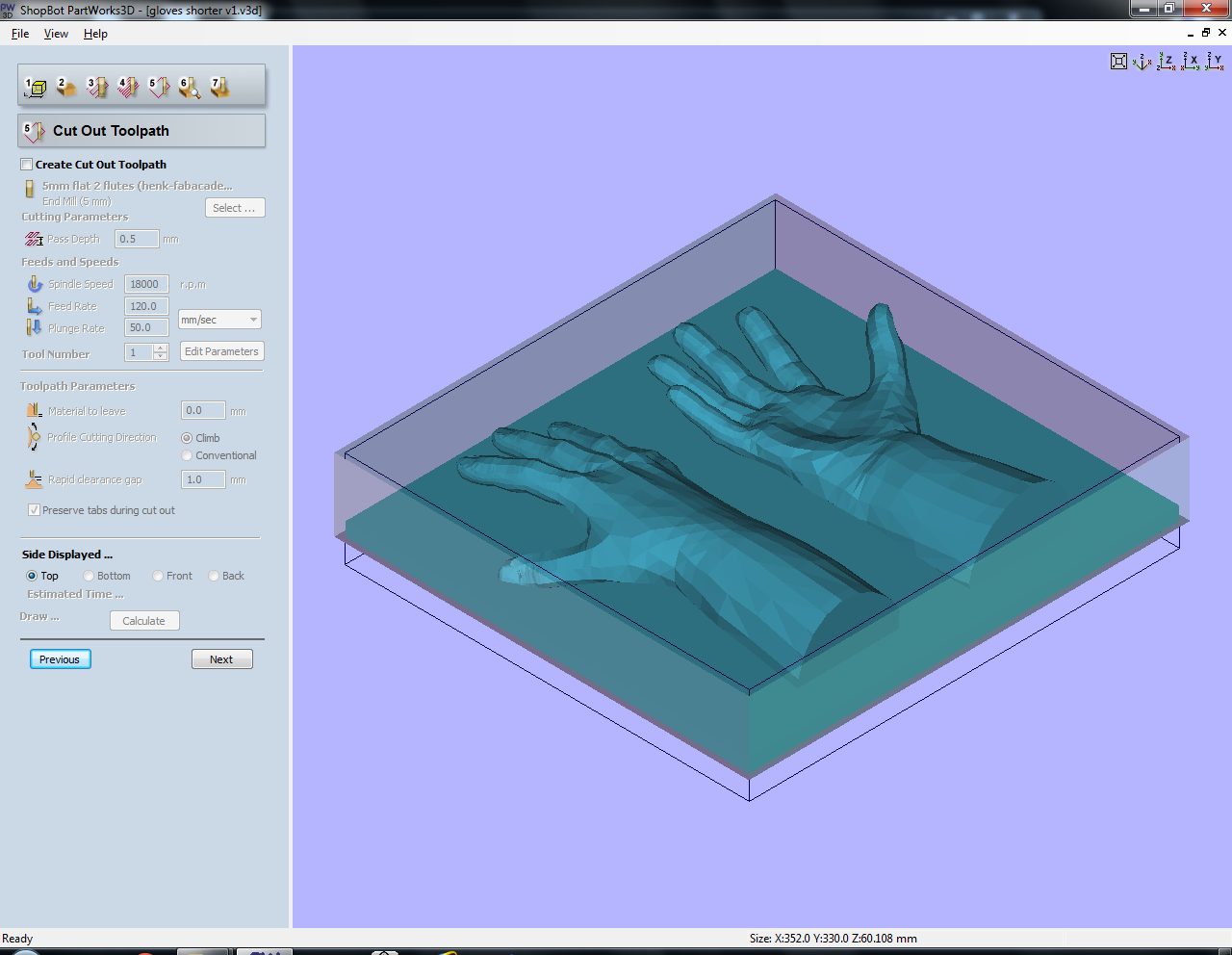
5. A Cut Out Toolpath
A cut out can be specified in this step but when using foam it’s much faster to do this by hand. If you need a perfect cut-out however this is the place to be.
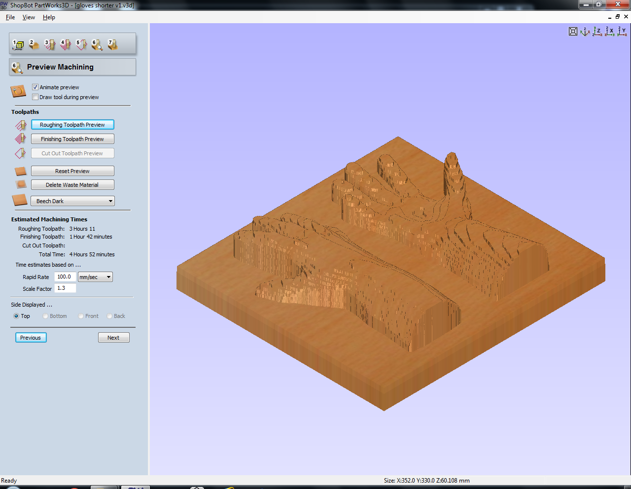
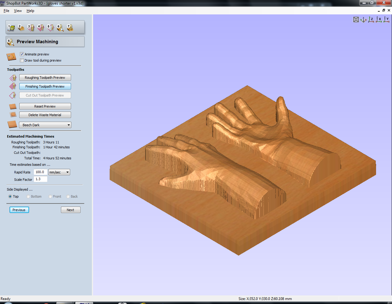
6. Preview Machining
In this step you can preview your toolpaths. Since the machine cannot mill under overhangs, it’s going straight down. It’s not a problem for this specific design, but you should keep this in mind while designing. You also have to take the diameter of the mill into account; some of the spaces between the fingers were too narrow to mill all the way through.
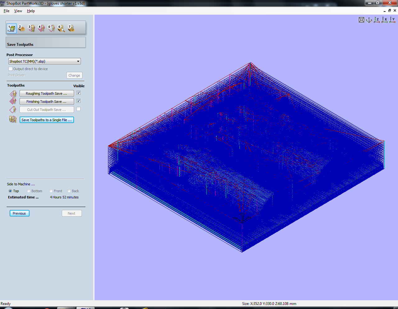
7. Save the toolpaths
Save the toolpaths to a single file if you don’t have to change the mill in between and want to do the whole design in one go, otherwise save them separately.