VCarve Pro tutorial
In this tutorial you’ll learn how to import and set up your files in VCarve Pro, the software we use to generate the gcode that instructs the Shopbot. If you want to make a 3D object such as a chair or box, consisting of multiple 2D panels, you need to mill in 2D. Before you can mill you need you need to prepare your vectors (in Fusion 360 or your software of choice). Save each face of your object in a 2D vector file. VCarve supports most vector files. Alternatively, you can also create vectors in VCarve. You can also use VCarve with 3D models.
Setting up your file in VCarve Pro
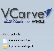
First, we open VCarve and create a new file.
-
Turn on the computer.
-
Open VCarve pro.
-
Create a new file.
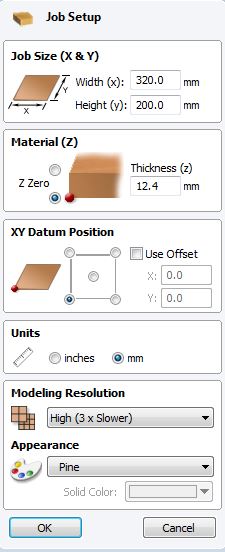
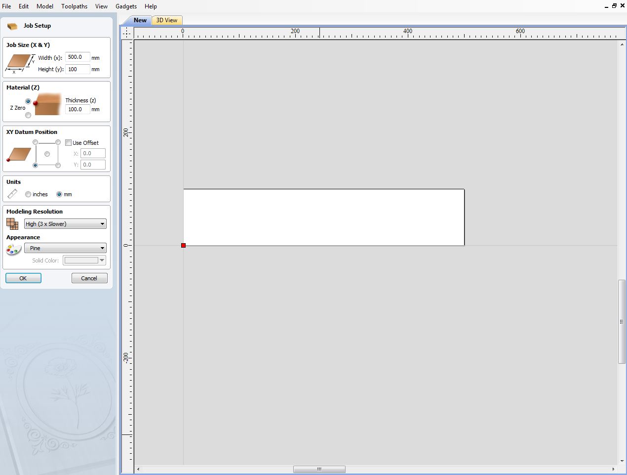
Job setup
Next we fill in the details of the material we’re working within the Job setup menu.
-
Job size (X & Y): Measure the width and height of the material.
You can either use the correct full-size width/height of the material, or trick the machine in thinking the material is smaller than its original size if your model is smaller than your material. If you set the dimensions of the material to the dimensions of the model, you can zero the machine where you want to start milling.
-
Material (Z): Set Z Zero at the bottom for 2D milling (zero on the sacrificial layer). For 3D milling, it can be more convenient to set Z Zero at the top of the material (if you’re working with a thick material that you’re not milling all the way through).
Measure the thickness of the material. You can use a digital caliper for this.
-
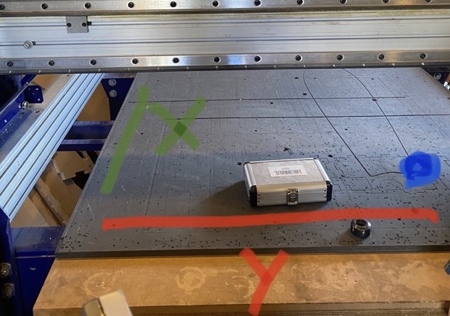
XY Datum position: Set the orientation point.
Be mindful of the orientation of the shopbot (see picture below). The bottom-left corner corespondents with the blue dot on the picture.
-
Units: Use mm
-
Modeling resolution: Not important, this only is used for rendering.
-
When finished, press “OK”.
Always keep the orientation of the CNC in mind. X-axis should be the (longer) side parallel to the wall, Y-axis should be the “open” (shorter) side. XY datum position should be the bottom left corner. When sitting behind the CNC-computer, line up the computer to correspond to the right orientation.
Tool (mill) types
Before we can setup the toolpaths, we need to know which mill we’ll use. When choosing a mill there are a few things to consider.
Diameter
This is the thickness of the mill. The thicker the mill, the faster and less precise. The thinner, the slower but more precise. Standard is 5mm.
Flutes
The number of threads of the mill. The more flutes, the more precise the milling, but also more slow.
-
One flute: For rough/prototype work. Fast, but not very neat.
-
Two flutes: Standard, more precise.
-
Four flutes: For very precise work. Slower.
The flutes are important for the speed of the machine, because the mill needs to drain the material. The more flutes, the more difficult to drain the material.
Tips
We mostly work with two kind of tips; End mills (flat) or Ball nose mills (rounded). We generally use the end mills. Ball nose mills are used for milling contoured surfaces.
Here are some examples of different mills:


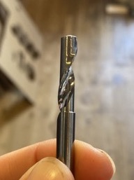
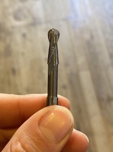
From left to right:
5mm 2 flute end mill - 3mm 4 flute ball nose mill - 6mm 1 flute end mill - 6mm 2 flute ball nose mill
Tool database
For every toolpath you’ll be asked to select your tool (mill) in the tool database.
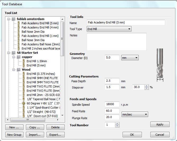
Tool info
The tool database will have a few settings to set:
- Name - Name of the tool
- Tool type - In Fablab we work with either End mills or Ball nose mills. Select which one you are using.
Geometry
- Diameter (D) - The diameter of the mill you’re using.
Cutting Parameters
-
Pass Depth - Maximum depth of the material removed per pass. Set this to half of the diameter of the mill. If using a 5mm mill, the pass depth should be 2.5.
-
Step over - Distance between each pass of the machine tool head. The larger the step over, the faster the job but the less precise. 100% step over is no overlap. 50% is half overlap. The lower the step over, the smoother the surface.
- Larger stepover: rough milling, fast prototypes.
- Small stepover: nicer material, nice finish, precise work. 30% is roughly in the middle - a good starting point
Feeds and Speeds
- Spindle speed - How many rotations per minute the mill makes. 18000 for wood is the standard & maximum speed. Changing this value here is only for your own information; you have to set this manually on the machine.
- Feed rate - How fast the mill tool head moves. Use 50 - 60 mm for wood with a 2 flute end mill. When you go slower the traces will be more neat, but the milling will also take longer.
- Plunge rate - Speed of going down, you can keep this on 20.
Vector files
Importing your file
Now its time to import your files. These are the steps for vector files; scroll down for the 3D instructions.
-
Go to “File -> Import -> Import Vectors”
Sometimes when you import a file lines disconnect. You can fix it in the VCarve.

-
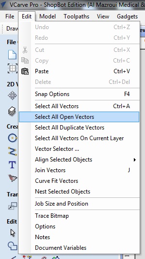
Check if there are no open/duplicate vectors. Delete if needed.
To select all open/duplicate vectors go to “Edit -> Select all open/duplicate vectors”
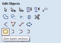
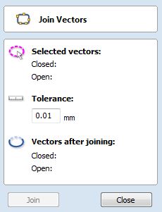
Go to “Edit object -> Join vectors (with tolerance)” to connect lines.
-
Use “Transform object” in the edit object menu to move or rotate objects.
Creating toolpaths
We create different toolpaths for milling.
The order of the toolpaths should be as following:
1 - drilling toolpath
2 - pockets toolpath
3 - inner cutting toolpath
4 - outer cutting toolpath
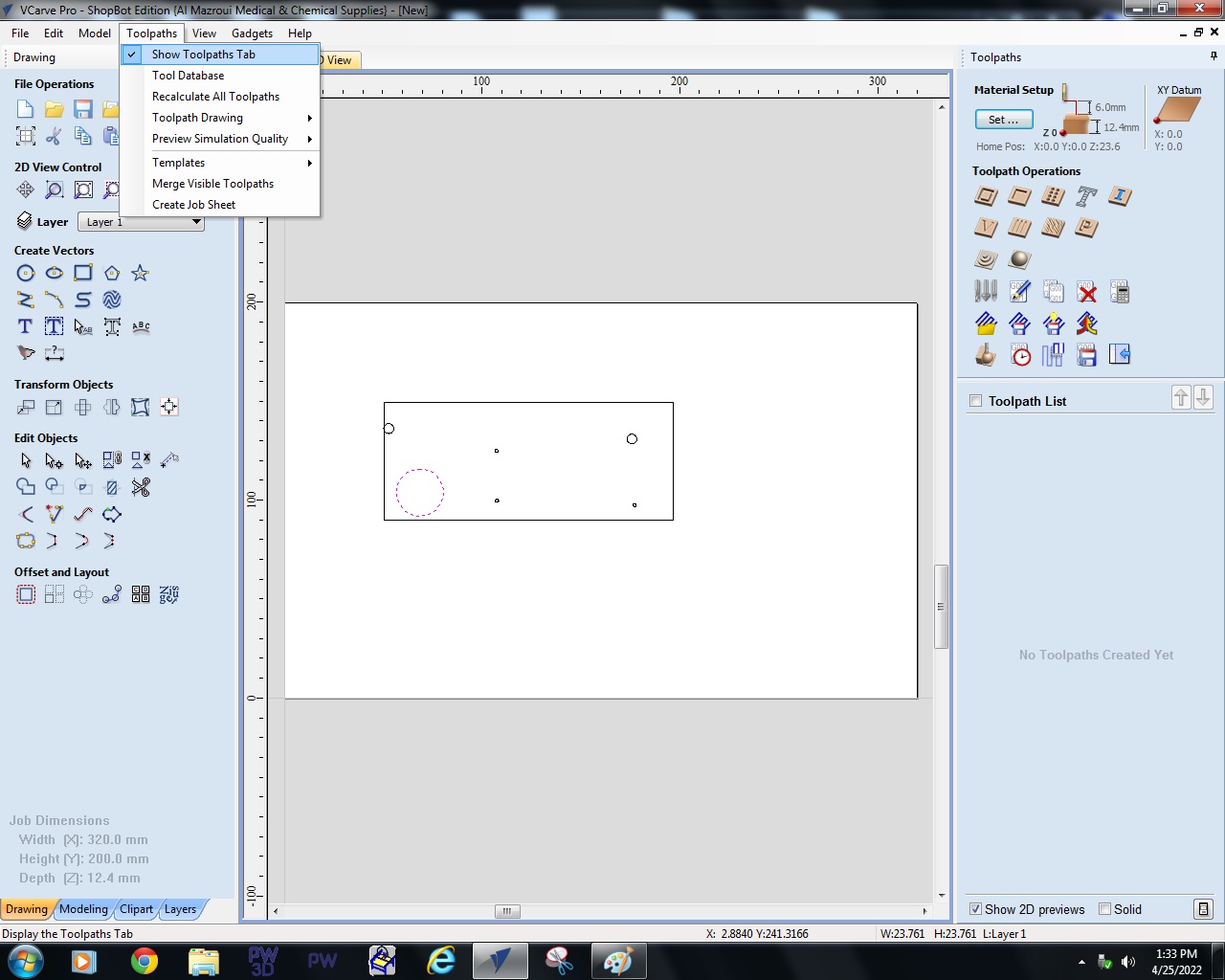
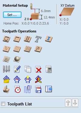
Open the toolpath menu:
Drilling toolpath
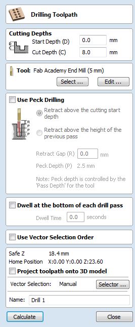
Drilling toolpath menu:
Use this toolpath to make holes for your screws to hold down the material when milling. Use the same size for the holes as for the mill. (If mill size is 5mm -> drilling hole size should also be 5mm). It’s very important that you first mill the drilling toolpath, then secure the screws, and then mill the other toolpaths. After the screws are secured the mill CAN NOT mill at the same location as the screws. This can result in sparks that can lead to a fire or explosion. So make sure to triple check that you haven’t selected any of the drill hole vectors after the drilling toolpaths.
-
Select the drilling holes.
(When using Vector selection order, the machine will mill the holes in the order of selecting)
-
Set start depth and cut depth
Start depth - If starting on the top of the material (most cases) start depth is 0 (Except for when drilling in a pocket).
Cut depth - You don’t want to cut all the way through because you want the screw to hold onto something. 2/3 of the material thickness is good
-
Select the tool in the Tool Database
When pressing select the tool database will open. Select the desired tool and settings.
Pocket toolpath
Pocket toolpath menu:

-
Cutting Depths
Start depth - 0 when you start on top of the material. When you’re making a pocket in a pocket, set the start depth to the depth of the pocket
Cutting depth - how deep your pocket needs to be.
-
Select the tool in the Tool Database
-
Clear Pocket…
Offset (square spiral) or raster (side by side). Works well with vectors, but not with 3D shapes.
Cut direction - Climb or conventional (doesn’t matter).
Raster angle - Set raster angle to match only moving the head of the machine.
Profile pass - Nice to do at the end to avoid ugly bits.
Pocket allowance - Will mill the pocket either smaller or bigger than the vector. (To make thing fit loosely or tightly)
Profile toolpath
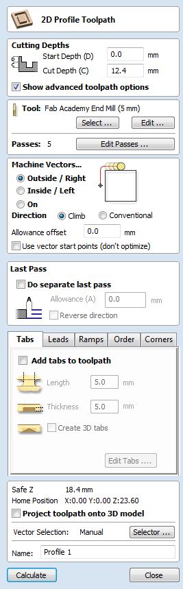
Profile toolpath menu:
-
Start depth - 0 when you start on top of the material.
Cutting depth - Material thickness when you start on top of the material.
-
Select the tool in the Tool Database
-
Machine vectors - Where to place the mill.
-
Separate last pass - This will make the trace smoother.
-
Tabs !! Important !!
Tabs are little nudges to connect everything to prevent pieces from moving during milling and being sucked up by ventilation. Make sure you add tabs around all your profiles; preferably no tabs on corners.
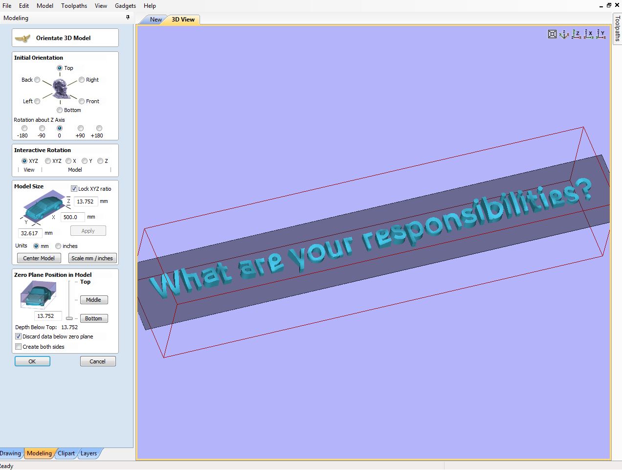
3D models
Importing your file
Your material should already be set up; the Z Zero is placed at the top of the material here.
- Go to “File -> Import -> Import Component / 3D Model”
-
Scale your model and place it in the material. Make sure that the side from which you want to mill is facing upward (Z). Set Zero Plane Position in Model to Bottom. Make sure everything is set up correctly because you can’t go back to this menu. Press OK.
-
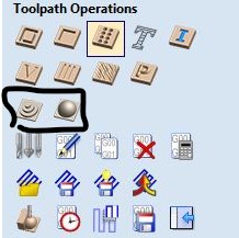
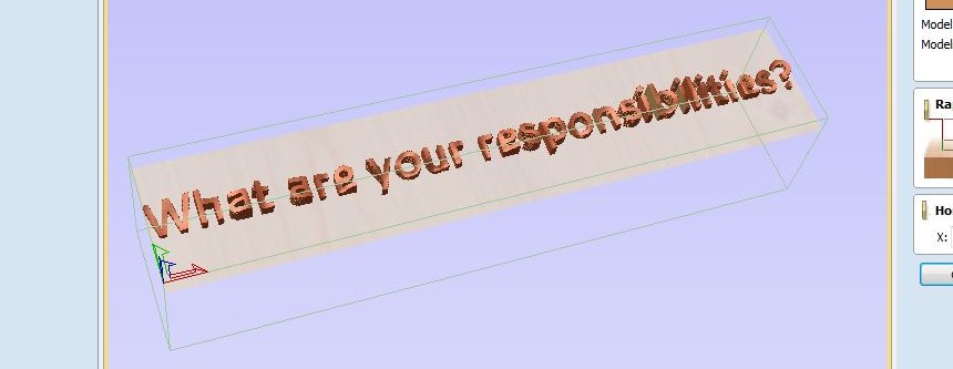
In the toolpath menu to the right, click Roughing Toolpath (the left one circled in the image). You will see the following menu for the Material Setup. You will only see this menu if you selected Z Zero as top in the Job Setup, but you can change that to bottom here. This is where you specify where your model is positioned in the material. Usually you want to place your model as high as possible, because then you’ll need less machine passes. If your material has an uneven surface you can set a gap above the model (here set to 1mm) to even out the surface. Double check everything because this menu will only show up once.
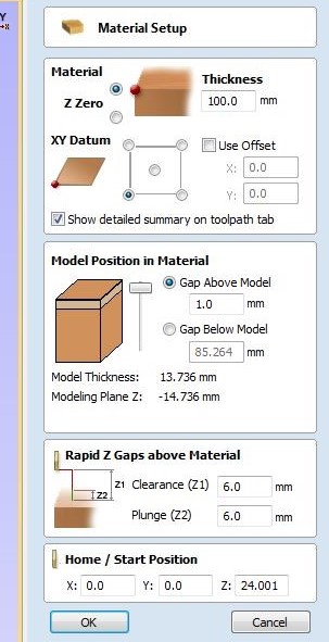
You can see where the model is placed within the material; the thin lines indicate the boundaries of the material.
Creating toolpaths
Roughing toolpath
-
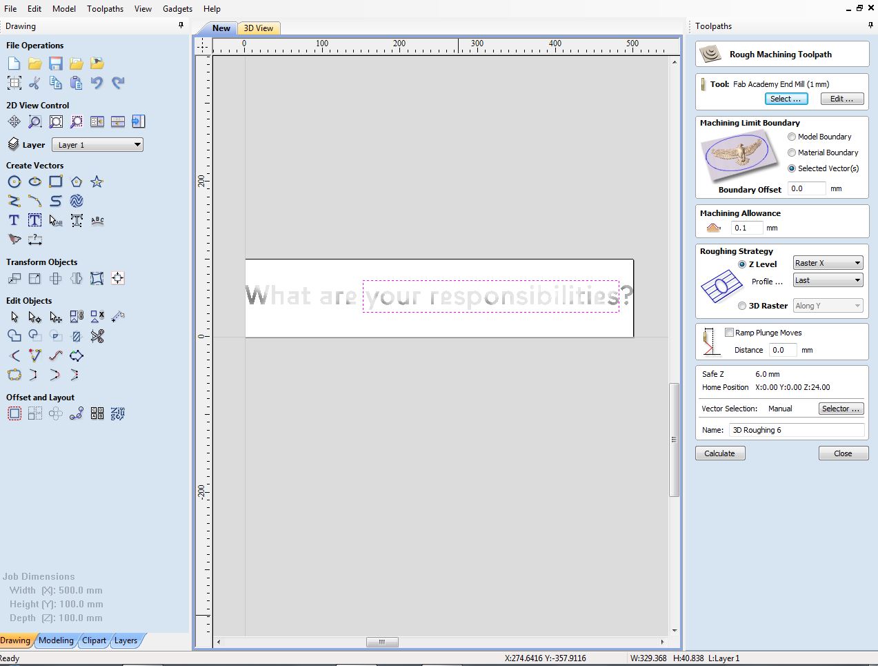
In the roughing toolpath menu start with selecting a milling bit. In this example a very small 1mm mill is used; that is generally not what you want to use (especially for roughing) as it will take very long.
- The machine limit boundary can be set to the model, the material or a vector. In this case a vector is used.
- A boundary offset is how far past (the middle of) the milling bit goes beyond the model or vector: this is useful for when you are milling a model that might otherwise not be fully machined to the edge.
- Machining allowance is what’s left to sand away after milling
- With a Z level roughing strategy the machine will mill material in a few passes (specified by the pass depth), Y axis is less hard on the machine. 3D Raster strategy will follow a nonplanar path. Press calculate.
-
After calculating you can see the movements of the milling bit.
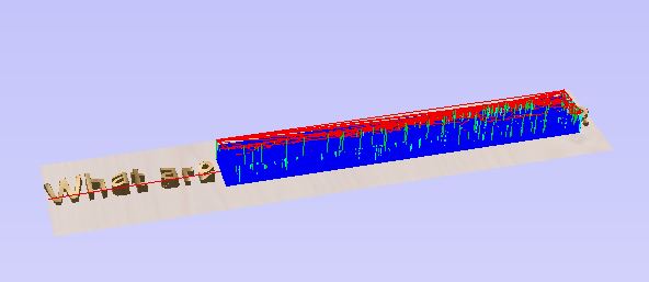
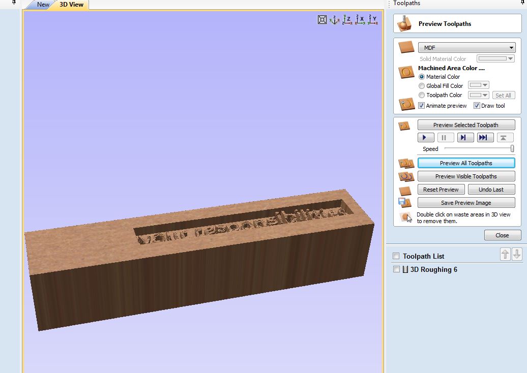
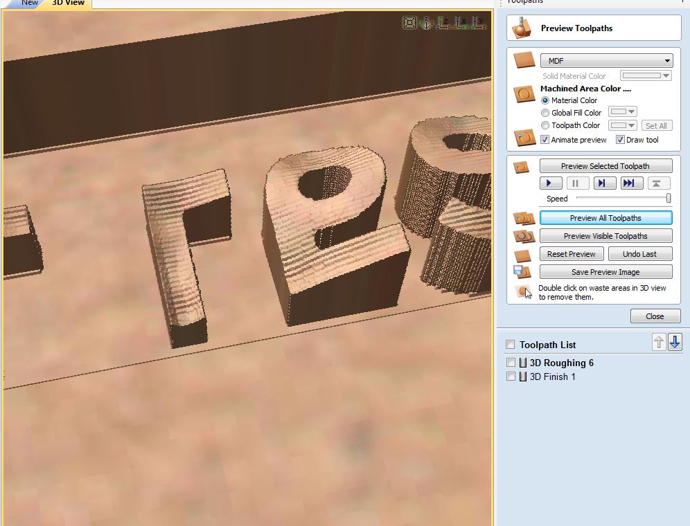
Go to Preview Toolpaths to see the result of the roughing toolpath:
Finishing toolpath
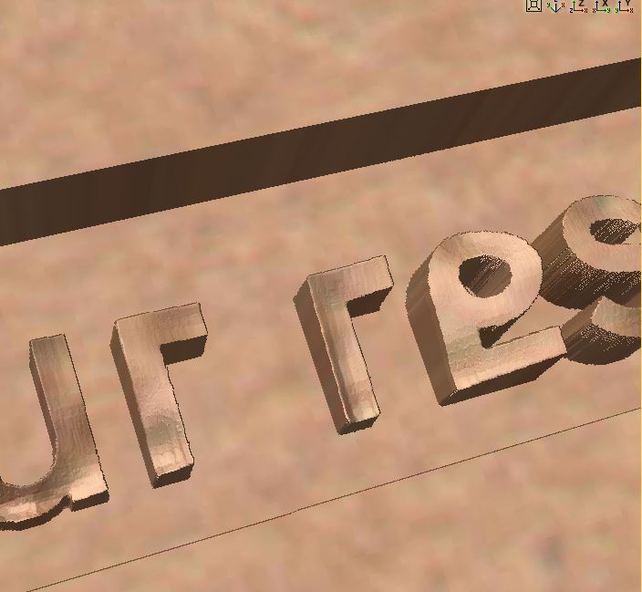
Then set up the finishing toolpath (the icon on the right in the menu picture above). Change tools and settings if needed. You can again set a Machining Limit Boundary; you usually pick the same one as you used for the roughing toolpath. Use the offset strategy when working with round shapes and raster for other shapes.
If the preview shows lines around the model like below, try tweaking the stepover in the finishing toolpath. On the left a stepover of 60%, on the right a stepover of 10%.
Notes
- If you need the negative of the model you’re working with: right click the model in the component tree and set combine mode to subtract
- If you have any weird jagged edges, try adding a zero plane (Model > Add Zero Plane).
- Use raster strategy according to material, try to align the grain with the Y axis so it’s less heavy on the machine
After creating the toolpaths
Save the file and name the toolpaths. Make sure the drilling toolpath is separate from the other toolpaths.
-
Clock icon - Use this to check how long milling will take.
-
Floppy icon - Save the toolpaths.
Save the drilling toolpath and the other toolpaths as separate files. Make sure you use the metric system. Save the files in a local folder.
!! Important - Check your file !!
Every time you change a file - Always calculate again! Never change anything after checking your files. (No recalculations etc. You don’t want anything changed because maybe you don’t notice a screw having a different location/or other dangerous situations occurring) Please breathe, don’t hurry. Milling is not something to do when you’re in a rush.
Triple check your settings. You can use the 3D view to see how the mill will behave.
If everything looks good you’re done with VCarve and ready to set up the shopbot software.
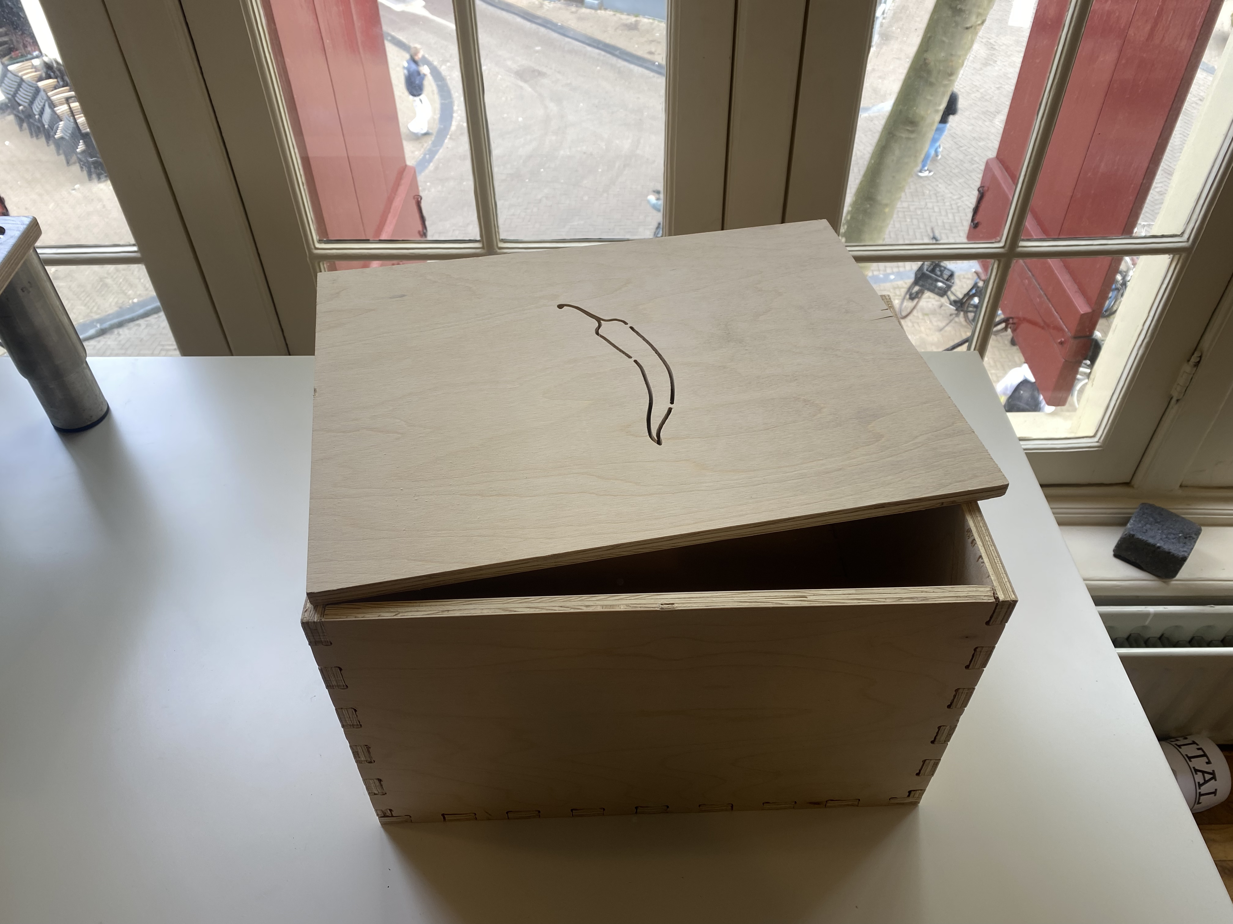
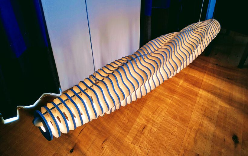
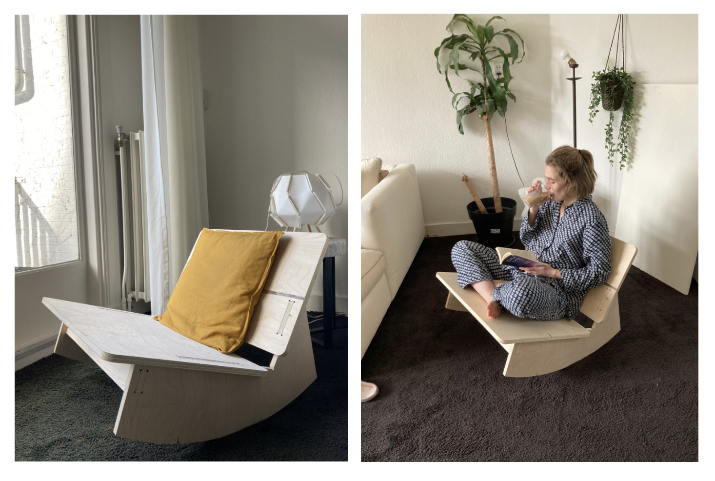
Made @ Fablab
Click the images to visit the documentation pages of the projects